
7 Tips for Choosing the Right Sieve Components

Choosing the right Sieve Components can determine whether a screening system runs smoothly or creates constant maintenance work. A mesh that looks suitable on paper may blind quickly when the material is damp. A frame that fits one machine may not seal properly in another. Small details matter.

Start with the material, not the catalogue. Consider particle size, moisture, abrasiveness, temperature, and the required throughput. Then check how the sieve operates: vibration pattern, deck dimensions, tensioning method, and cleaning system all affect component performance. Ask suppliers for material specifications, dimensional tolerances, and test information relevant to your process. Where possible, compare samples under realistic conditions. A few hours of observation can reveal problems that a product description cannot.

There is no universal best choice. Stainless steel may suit some environments, while other applications call for different alloys or polymer parts. The right option depends on operating conditions and maintenance priorities. Think about replacement intervals, spare-part availability, and the practical time needed for a changeover. Those costs are easy to overlook. A cheaper component can become an expensive choice if it wears rapidly or interrupts production. Even careful selection has limits; actual feed material can vary from batch to batch. The following seven tips offer a practical framework for comparing Sieve Components, asking better questions, and making a more informed decision. A little doubt helps. Verify assumptions before committing.
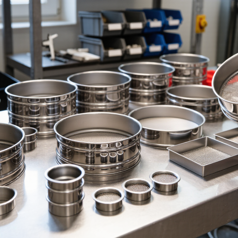
7 Tips for Choosing the Right Sieve Components

Define Separation Targets by Aperture Size: ASTM E11 Covers 20 µm–125 mm

7 Tips for Choosing the Right Sieve Components

Define the separation target before selecting a sieve. ASTM E11-24 covers standard test-sieve apertures from 20 µm to 125 mm. That range spans fine powders and coarse aggregates. The standard also sets requirements for sieve cloth and construction, so aperture size is only part of the specification. Small gaps matter. For example, 75 µm and 150 µm sieves can separate noticeably different fractions in a fine powder. A sieve set should bracket the target size, rather than rely on one opening alone. Sample shape and moisture can complicate a clean size cut; the nominal aperture will not explain every result.

Tips: Write the required cut size in micrometres or millimetres, then choose the nearest ASTM E11 opening. Check the full sieve series for useful steps above and below that target. Confirm the sieve designation as well as the aperture; labels can be misread during busy sample preparation.

For reliable comparisons, record the standard, aperture, and sample condition with each test result. ASTM E11’s specified aperture range gives teams a common reference, but test results still depend on handling and method. Keep the sieve clean, inspect the mesh for damage, and avoid forcing particles through openings. It sounds obvious. It is easy to overlook after repeated runs. A brief inspection before testing can catch blocked or distorted mesh before it affects the separation.

Choose Mesh Material for Process Conditions: 304 vs. 316 Stainless Steel

Choosing between 304 and 316 stainless steel starts with the process, not the price. Grade 304 suits many dry, mild, or low-corrosion applications. Grade 316 contains molybdenum, which generally improves resistance to chloride-related pitting. That can matter when screening salty products or using chloride-bearing wash water. Neither grade is immune to corrosion. Temperature, chemical concentration, cleaning frequency, and contact time all affect performance.

Tip: Check the full process conditions, including wash cycles, before selecting mesh. A chemical name alone may not tell the whole story. Confirm compatibility with a qualified materials specialist, and test the mesh under realistic operating conditions when failure would disrupt production. Small details matter.

Inspect mesh after use. Look for pits, discoloration, broken wires, or openings that have stretched. These signs deserve attention, but discoloration alone does not prove corrosion; residue or contamination may be responsible. A magnet is not a reliable way to identify the grade. In practice, it is easy to focus on the alloy and overlook wire thickness or mesh opening. That choice can affect both screening accuracy and service life. Revisit the selection if conditions change.

7 Tips for Choosing the Right Sieve Components - Choose Mesh Material for Process Conditions: 304 vs. 316 Stainless Steel

Selection factor 304 stainless steel mesh 316 stainless steel mesh Practical selection tip
Typical alloy composition Commonly contains about 18–20% chromium and 8–10.5% nickel. Commonly contains about 16–18% chromium, 10–14% nickel, and 2–3% molybdenum. Check the material certificate and applicable specification; exact composition limits depend on the grade standard.
General corrosion resistance Offers good corrosion resistance in many indoor, dry, and mildly corrosive service conditions. Molybdenum generally improves resistance to pitting and crevice corrosion compared with 304 in chloride-bearing environments. Match the alloy to the actual process liquid, concentration, temperature, and exposure time—not just the product name.
Chlorides and salt exposure May be more susceptible to pitting or crevice corrosion in chloride-containing service. Often the more suitable of the two for moderate chloride exposure, but it is not immune to chloride attack. For seawater, concentrated chlorides, or warm chloride solutions, consult corrosion data or a materials specialist before selection.
Typical process examples May suit general dry screening, many food-handling applications, and non-chloride process conditions when the required grade and finish are specified. May be preferred for salt-containing ingredients, some chemical environments, or frequent exposure to chloride-bearing wash water. Confirm compatibility with every product and cleaning chemical used in the process.
Cleaning and sanitation Can be used in many washdown applications, depending on cleaner chemistry, concentration, temperature, and contact time. Often provides a wider corrosion-resistance margin with chloride-bearing cleaners, but cleaning conditions still matter. Specify cleaning agents and sanitizers early; rinse and dry practices can affect corrosion risk for either alloy.
Mesh performance Opening size, wire diameter, weave, and fabrication determine filtration and much of the mechanical behavior. Opening size, wire diameter, weave, and fabrication determine filtration and much of the mechanical behavior. Choose aperture and wire dimensions from the separation and load requirements; alloy selection alone does not define mesh performance.
Relative material cost Usually the lower-cost option when its corrosion resistance is adequate for the process. Usually costs more because of its alloy content, including molybdenum. Compare total service life and replacement risk, not purchase price alone.
Verification before ordering Confirm grade, wire diameter, aperture, weave, finish, and required documentation. Confirm grade, wire diameter, aperture, weave, finish, and required documentation. State the process chemistry and operating conditions in the specification, and verify material traceability when required.

Important: Corrosion performance depends on the complete operating environment, including chemical composition, concentration, temperature, surface condition, and crevices. Neither 304 nor 316 is suitable for every process condition.

Balance Wire Diameter and Open Area Using the Square-Mesh Formula

Choosing sieve components starts with a practical trade-off: larger openings pass material faster, while thicker wires can improve durability. For square mesh, estimate open area with this formula: open area (%) = [opening ÷ (opening + wire diameter)]² × 100. Use the same units for both measurements. For example, a 1.0 mm opening with a 0.25 mm wire gives about 64% open area. Small changes matter. Increasing the wire diameter reduces the available area, even when the opening stays fixed.

Use the estimate to compare options, not as a promise of actual throughput. Particle shape, moisture, vibration, and material buildup can all affect performance. A fine powder may need more open area to maintain flow, but a very thin wire can wear or deform sooner under heavy use. Check the sieve’s operating conditions and inspect samples under realistic loading. It is easy to overvalue a neat calculation; real material rarely behaves so neatly. Record the opening and wire dimensions, then verify separation quality and flow during a controlled trial.

Balance Wire Diameter and Open Area

For a square mesh with a fixed 1.00 mm aperture, increasing wire diameter reduces open area. Values are calculated using the square-mesh formula: Open area (%) = [aperture ÷ (aperture + wire diameter)]² × 100. Consider the trade-off between material strength and flow or screening area when selecting sieve components.

Match Sieve Frames and Tolerances to ASTM E11 or ISO 3310-1

A sieve is only useful when its frame, mesh, and stated tolerances suit the test method. ASTM E11 and ISO 3310-1 both specify requirements for test sieves, but their classifications and acceptance criteria are not automatically interchangeable. Check which standard your procedure names before ordering replacement components.

Compare the nominal aperture with the permitted variation, not just the number printed on the label. For example, a sieve marked 500 µm may have defined limits for individual openings and average opening size. Ask for documentation identifying the standard and edition, and confirm that the supplied mesh was inspected against its requirements. Paperwork matters.

The frame must also fit the sieve stack and shaker. Measure its diameter and height, then check how the rim seats against neighboring sieves. A small mismatch can cause movement, dust leakage, or uneven handling. For wet or corrosive samples, consider frame and mesh materials that tolerate the cleaning method. Do not assume a familiar frame size means the tolerances match. It may not.

Before use, inspect the mesh under good light for dents, blocked openings, or loose joints. Record the sieve identification and condition, especially when results need to be compared over time. Standards help set a reliable baseline, but actual fit and maintenance still deserve attention. Sometimes the overlooked rim causes the trouble.

Check Wear, Blinding, and Throughput Before Finalizing Components

Before finalizing sieve components, inspect the parts that face the most abrasion: mesh intersections, frame edges, and seals. Note thinning wires, stretched openings, loose joints, or polished patches; these can signal wear before a tear appears. Use a light and magnifier, then compare aperture measurements with the original specification. Small changes matter. A mesh that has opened slightly may pass oversized particles, while a worn seal can let material bypass the screen. Photograph defects and record operating hours. Visual checks can miss early fatigue, so measurements deserve equal weight.

Check blinding during a representative run, not only with clean material on a bench. Damp fines may cling to the mesh; angular particles can lodge across apertures. Watch for blocked areas, rising material depth, and uneven discharge. Then log feed rate, product size, and screening time. Compare throughput under the same feed conditions, since a faster run can sacrifice separation quality. Try a short trial with the proposed mesh and cleaning method. It may not predict every shift. Still, note where performance drifts, how often cleaning is needed, and whether wear accelerates. These imperfect observations can reveal issues a single good batch may hide.

Call Now Button